Early Theatre Winch Controls
In the early days of Theatre Consulting as a profession, some consultants were much more hands-on when it comes to the design of equipment to solve a particular need. As the saying goes, “necessity is the mother of invention”. Jim Read, FASTC shares some thoughts on his early work with consulting pioneer, George C. Izenour, and how early winch controls were developed.
ASTC: Jim, tell us about your experience developing winch controls for theatre.
Jim Read [JR]: When you see the sky-cam over a football arena or Cirque du Soleil performers flying around the room, have you ever wondered how it all began? I doubt many have considered how the winches that move these objects are positioned. Obviously, the cables are drawn in and out by electrically controlled mechanical winches. To do this, there must be some form of feedback from the mechanical winch to the electrical control circuitry. The control technology for theater winches was initially developed in the late 1950s by George C. Izenour, and further developed in his laboratory at Yale in the early 1960s by me.
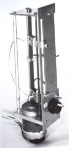
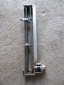
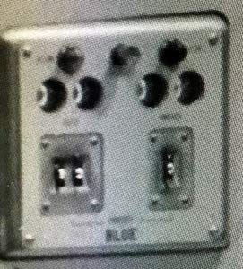
When Izenour introduced the spot line winch system, he used what he called a telemeter, a console read-out that indicated the position of the winch and provided an adjustable travel limit. A synchronous motor was attached to a winch drum and electrically connected to a similar synchronous motor at the telemeter which turned a leadscrew, moving the telemeter indicator up and down proportional to cable deployment as the winch drum rotated. When the drum turns, the console telemeter indicator would move up or down to the limits set by the operator. This was a closed-loop analog control system.
This arrangement worked fairly well as long as the system was energized. However, during switching or when the system was powered down and then turned on later, the register between the winch mounted and telemeter synchronous motors were not likely to start in the same register, resulting in the position indicator incorrectly showing the winch position. The system worked reasonably well for flying drapes and things that did not have to contact the floor.
ASTC: How where these problems resolved?
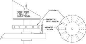
JR: Less than satisfactory performance at Hofstra and Harvard resulted in a new approach by Izenour designed to improve positioning reliability. He proposed an open-loop, digital control system that would generate an electrical pulse for each inch of cable travel. Counting the pulses would measure the distance the load traveled to an easily adjustable limit. It was designed around a series of magnets implanted in a disk mounted to the winch drum shaft that would activate a magnetic reed relay generating an electrical pulse for a predetermined–one inch, in this case–amount of cable travel.
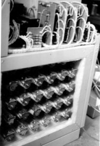
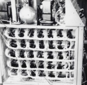
This approach required a device that could count pulses, providing a register of how far the cable had traveled. I began development, and subsequently produced four production models of a cascaded relay ring counter that could count in inches, feet, and tens of feet as fast as the 24 pulses per second (120 feet per second) generated by the maximum cable velocity.
The control panel provided selector switches to set the desired travel distance, and a numeric display of distance traveled in feet and inches. Hard-wired, the control system initiated “Slow Down” and “Stop” to the winches.
ASTC: It sounds like this was an improvement. How reliable was it?
JR: Well, the difficulty with this approach was the pulse relay was occasionally sporadic, and if one pulse was lost, then an inch of cable travel was not accounted for – a large error for scenery when you’re trying to put it on the floor gently. Though there were occasional miscounts of the pulse train, the system was reliable enough to be used successfully in a design at Dartmouth University.4
To improve positioning performance, a more accurate feedback system was required. This implied that each pulse must represent a smaller division of the inch, but one pulse per inch was already operating the counting chains, which were electro-mechanical devices, at near maximum frequency. The obvious solution was a purely electronic device capable of counting at frequencies.
ASTC: An electronic version seems more like a modern approach we might see today.
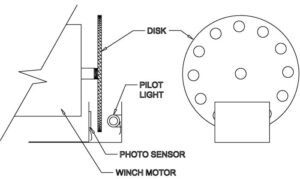
JR: Yes. I developed a new transducer to generate pluses using a pilot light, a perforated disk driven by the motor shaft, and a “solar” cell light-sensitive device to generate the pulses. The mechanics of the winch motor, gearbox, and drum diameter allowed a pulse to represent 1/40th of an inch. Electronic circuitry divided the pulse train by 10, allowing ¼-inch adjustment to the inches, feet, and tens of feet. After another division by 4, the pulse train was sent to the same relay counter as in earlier versions. With this system, if one or two pulses were lost it would not be significant. Reliability improved further.
The control panel for this system again provided switches to set travel distance in feet, inches, and quarters of an inch. A new development in “nixie” tubes–an electronic device using glow discharge–displayed a glowing pointer adjacent to the numbers on the bezels. That gave a real-time indication of how far the winch load had traveled.
ASTC: So, was this finally acceptable in terms of repeatability and reliability?
JR: Well, to a degree. This system performed well for the Foothill5 system and beyond. It also provided a means to test the accuracy of the synchronous winch system. A weeklong series of tests of the system uncovered the ultimate flaw in the design which turned out to be mechanical, not electrical. The test would measure the distance from the floor to a batten, run the batten up a given amount of travel and run it back down the same distance, then measure the distance from the batten to the floor once again. For unloaded battens the accuracy was excellent but loaded battens would be lower than their starting distance from the floor. The heavier the batten, the greater the distance variance was. Even after slowing the winch down, the delay from the “STOP” command to the setting of the brake allowed the loaded battens to drop lower for each cycle.
ASTC: Did your lab keep working on this?
JR: The system was turned over to J R Clancy and no further development occurred in our laboratory. Obviously, the technology has advanced to the point where accuracy is no longer an issue and similar techniques are used extensively in many different applications. These were crude devices that worked with some success, and at least turned out to be in the right direction.
As told by Jim Read, FASTC Emeritus
Footnotes
1 Kalita Humphrey Theater, Dallas Theater Center, Dallas, Texas
2 Hofstra University, Hempsted, New York
3 Loeb Drama Center, Harvard University, Cambridge, Massachusetts
4 Hopkins Center for the Arts, Dartmouth College, Hanover, New Hampshire
5 Foothill Junior College, Los Altos Hills, California
Disclaimer: Any views or opinions expressed in this article are solely those of the author and do not necessarily represent those of the American Society of Theatre Consultants. This article is for general information only and should not be substituted for specific advice from a Theatre Consultant, Code Consultant, or Design Professional, and may not be suitable for all situations nor in all locations.
Click on any image to enlarge


